Overview
The MAD CNC Plasma is built from many components working together. This section is intended to introduce the major working parts, familiarize you with the vocabulary used to describe an automated CNC plasma, and introduce the plasma cutting process. With this foundation in place, we can then explore the software workflow in later sections.
CNC?
In case you were wondering, Computer Numerical Control (CNC) refers to a computer interpreting a very simple numerical language commonly referred to as G-Code (RS-274). These programs are made up of moves to numerically defined locations, coupled with actions (M-Codes) like turning on a plasma torch.
Components of the Machine
The important components of the machine are called out in the following figure:
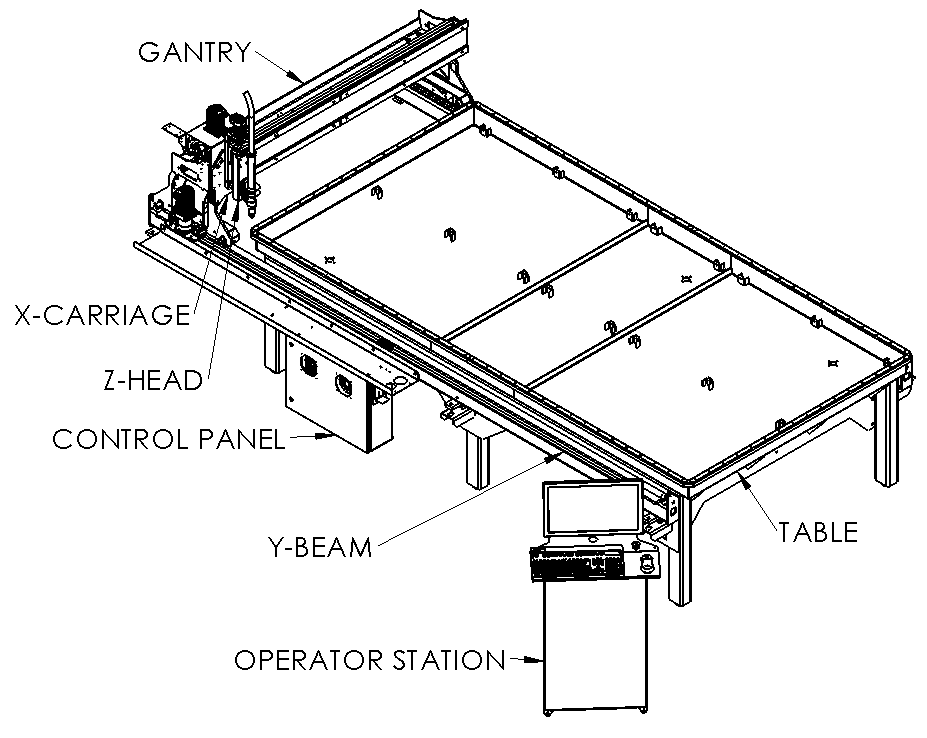
- Table - The work area of the machine that supports material to be cut.
- Y-Beams - The long rails that allow for motion forward and backwards. These fixed beams support the moving components of the machine.
- Gantry - Moves along the machine Y-beams and allows motion of the X-Carriage left and right.
- X-Carriage - Moves along the gantry and supports the Z axis. It also provides docking stations.
- Z-Head - The Z-Axis assembly allows for motion up and down. It also provides an automatic alignment system for the magnetic breakaway tool holders.
- Control Panel - Houses all sensitive electronic components.
- Operator Station - Communicates with the controller to "show" us what the machine is doing.
Exploring a little deeper, look inside the control panel:
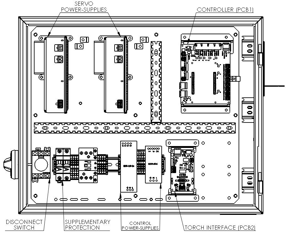
- Disconnect Switch - The main power switch for the machine. Turn to the On location to power the machine for operation.
- Supplementary Protection - An additional line of protection integrated in the machine. These components and fuse protection in each of the power supplies form the internal protection scheme. Primary protection must be provided externally.
- Servo Power Supplies - The power supplies that produce 75VDC for the servo motors.
- Control Power Supplies - The machine has multiple power supplies which isolate hazardous voltages from sensitive electronic components. These operate at 24VDC or 5VDC.
- Controller (PCB1) - This is the "brain" of the machine.
- Torch Interface (PCB2) - The board responsible for communicating with the plasma unit and providing isolation from potentially high voltages.
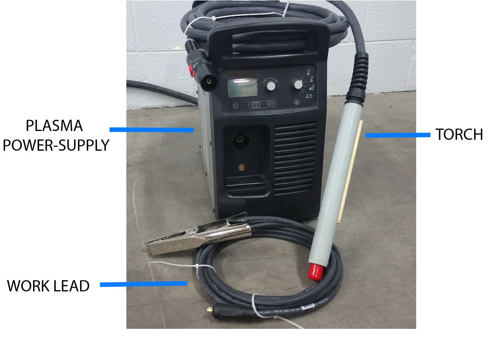
The components of a typical plasma system come next:
-
Plasma Power Supply - The box that the torch and work leads connect to that converts wall power to the current required to cut metal.
-
Plasma Torch - The torch is mounted to the CNC machine head and holds the cutting consumables. Combined with the work lead, it creates an electrical circuit that allows us to cut conductive materials such as steel, stainless steel, and aluminum.
-
Plasma Work Lead - The second half of the plasma electrical circuit. Commonly referred to as the plasma ground. The plasma work lead is bolted to the machine bonding bar, and the work clamp from the bonding bar must be connected directly to the work piece being cut.
-
Plasma Consumables - The components that mount to the torch such as electrodes, shields, and nozzles. These are wearing components and will be periodically replaced.
The control panel is connected to the plasma power supply via the machine interface cable. This cable provides control and feedback signals that allow the machine to ask for the plasma arc to turn on, and to measure the cutting voltage.
Axis, Home, Work-Offsets, What?
An axis is a direction of motion that the machine can travel along. The MAD CNC Plasma has 3 axes of motion in its default configuration (X, Y, and Z) shown below. Looking at the front of the machine, the X-Axis moves from left (-) to right (+), and the Y-Axis moves from front (-) to back (+).
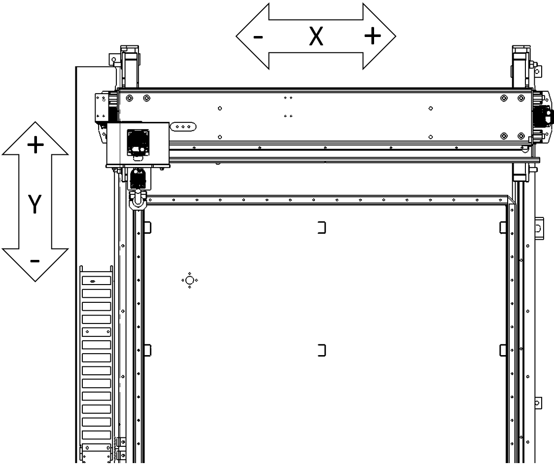
The Z-Axis moves from down (-) to up (+). There are stickers identifying each axis and their direction attached to the covers of the machine as a quick reference during operation.
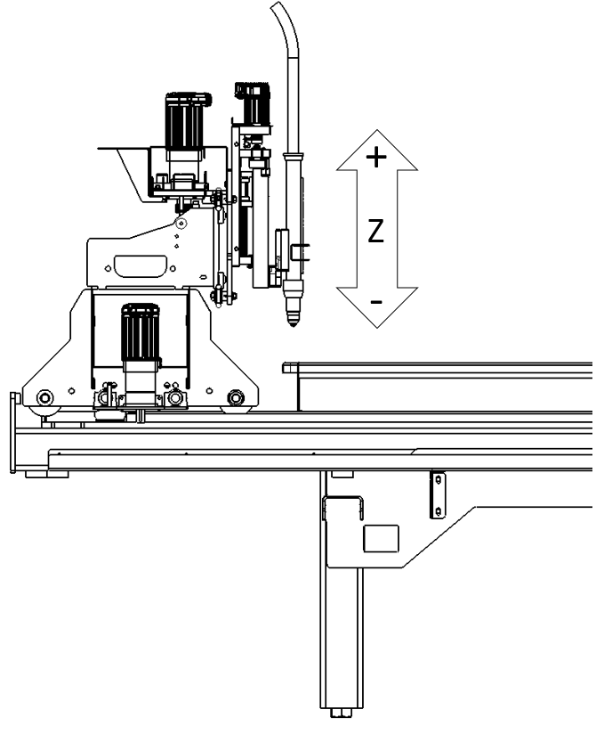
We can combine the directions of motion together with a reference point known as Home. For the MAD CNC Plasma, this location is the maximum left-rear-up position. The machine can move to any position inside the work volume, and the distance from the current location to the Home point describes the Machine Coordinates (MC). Here is a simplified drawing to narrow our focus:
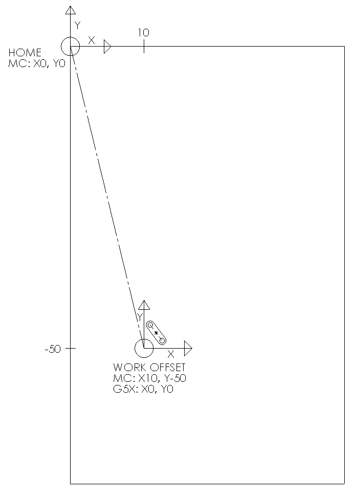
In the image above, we are looking down on the table along the Z-Axis. There is also another coordinate drawn as G5X. This work-offset allows us to define a relative position anywhere on the table to cut our parts. We export our cutting program relative to a local origin, and then tell the machine where that point exists. In the example drawing, the X and Y locations generated will always be positive values relative to the G5X system, even though the Y locations are negative in Machine Coordinates. Actual operation details will be explained later. For now, just take away that we can weave our parts into a plate or sheet by moving this point around without having to return to the CAM software. By default, the MAD CNC Plasma is configured to use the G54 work-offset, but there are many user controllable work-offsets ranging from G54 to G59.3.
Emergency Stop
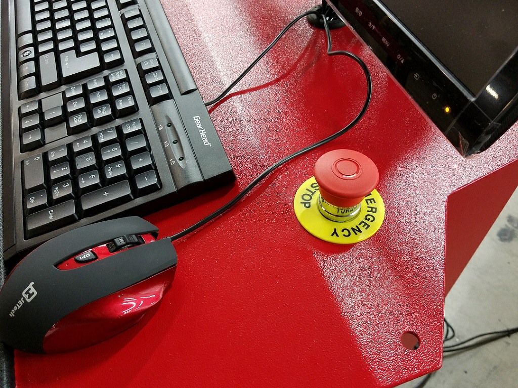
When the Emergency Stop Button is depressed, power is immediately removed from the servo drives halting machine motion and cannot be restored until the condition is cleared. After clearing the emergency condition, release the button by rotating or pulling the red cap, and repower the amplifiers. You will be forced to rehome the Z-Axis, but it is highly recommended to rehome the entire machine (X, Y, and Z axes) before continuing operation.
Magnetic Breakaway
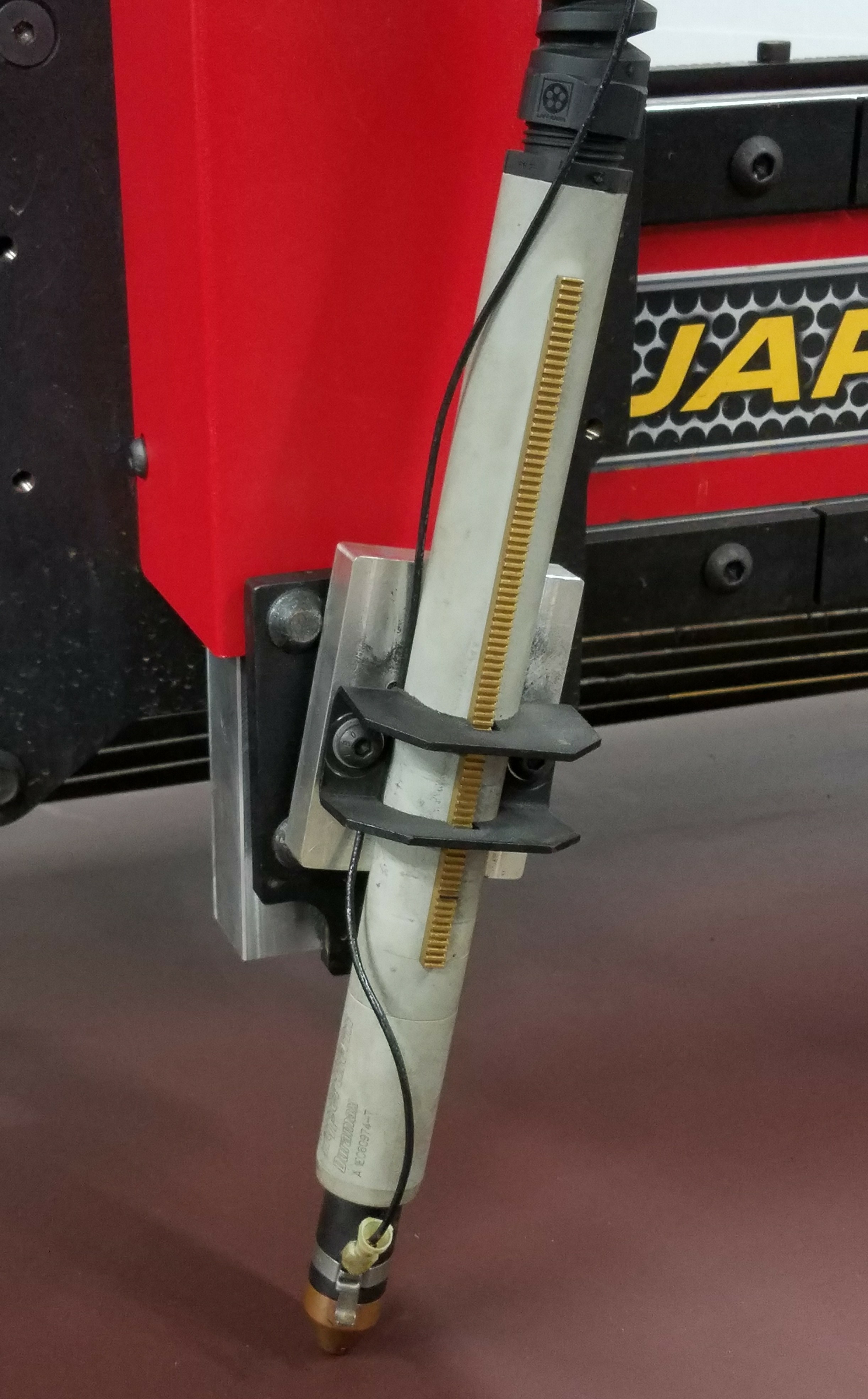
If the torch hits an obstacle sufficiently hard, the magnetic breakaway releases to minimize damage. This condition is identical to an emergency stop. Power is immediately removed from the servo drives halting machine motion. Again, you will be forced to rehome the Z-Axis, but it is highly recommended to rehome the entire machine (X, Y, and Z axes) before continuing operation. For instructions on clearing a breakaway condition, see the breakaway section of machine operation.
Ohmic and Floating-Head Probes
The MAD CNC Plasma table has two methods of probing along the Z-Axis to find the height of a workpiece: Ohmic and Floating-Head. Both methods have advantages and disadvantages, which is why the combination of the two is provided.
Ohmic probing requires specific consumables that allow connecting a wire directly to the shield of the plasma torch. When the shield touches a conductive (metal) surface, an electrical connection is made that the machine control can detect. The major advantage of this probing method is being able to detect the proper height of thin materials, especially when they are not perfectly flat. It does not rely on moving the weight of the Z-Head assembly, which means it detects the height of the material after it springs back. Unfortunately, this system does have trouble if it gets wet (since the cutting fluid is conductive with the addition of the metallic particles produced during cutting). Therefore, it is important to make sure the consumables are clean and dry before beginning a cut, and that there are no puddles on the surface of the plate. The Ohmic probe will sense a false positive at the surface of the water in a puddle, rather than the material underneath.
Floating-Head probes are a very simple, robust system. They do not rely on conductivity of the material, which allows it to successfully probe rusty or coated materials. It is not "fooled" by small puddles of water; it will even function correctly if the workpiece was fully submerged! The major downside to this probing method is due to the requirement of lifting the weight of the Z-head to trigger the mechanical switch. This weight, approximately 7 lbs., will flatten a thin piece of metal, and incorrectly measure the flattened height. As the head moves up, the material will spring back up, and an incorrect pierce height is established. In thicker materials, the probing accuracy of a calibrated floating-head is very good.
Automatic Torch Height Control
When a plasma torch is operating, a voltage is produced. A great property of this voltage is being proportional to the distance between the torch and the workpiece. Automatic torch height control (ATHC) is a simple system that takes advantage of this property to control the Z height when enabled. It does this by evaluating two rules against a reference or Cut Voltage:
- If the measured voltage is higher than the Cut Voltage move down.
- If the measured voltage is lower than the Cut Voltage move up.
This works great in normal operation. As a plate warp moves up or down, the voltage will shift down or up and cause one of the rules to take effect. In response, the ATHC moves the head. Repeat this 1000 times per second, and the torch tracks the contour while moving at the requested Cut Feed.
Remember, if the torch is not active, there is no voltage to measure so ATHC does not function!
Rule #1 of Operating Automatic Torch Height Control
Never run off the edge of the plate. This causes the plasma arc to approach open circuit voltage (very high), and makes the ATHC plunge due to Rule 2. Plate edges are sneaky, however, and may look like pierce points, previous cut paths already traversed, or previous parts that have fallen away - not just the outer edges of the plate being cut.
Automatic Torch Height Control Gotcha
The rules listed are all the ATHC uses while in operation. If we supply a reference voltage that is too low, the machine will plunge into the plate trying to reach that value. Conversely, if we supply a voltage too high, the machine will rapid away from the plate trying to reach the desired voltage. Extreme conditions could result in a long-arc. The reference voltages supplied by plasma manufacturers are measured at a given feed rate. If the machine is running faster or slower than this rate, it is very important to disable ATHC to avoid a crash.
Phases of a Plasma Cut Operation
For our purposes, we can think of a plasma cut having three distinct phases: initial height detection, piercing, and cutting.

Phase 1 - Initial Height Detection (IHD)
When a new plasma cut begins, the machine does not have an accurate height of the workpiece. This is due to different thicknesses of material, plate warpage or bow, or even plasma torch adjustment locations in the mounting bracket. To prolong the life of consumables, and to get an accurate cut, we need to correctly "find" the top of the plate. This process is called Initial Height Detection (IHD). The machine uses the Ohmic or the Floating-Head probe to determine this zero height.
IHD Modifications
-
IHD is skipped entirely and the machine is moved directly to pierce height if:
- IHD has been performed at least once.
- The current location is less than the Skip Probe distance from the previous IHD location. The default distance is 0.5" (12 mm).
-
IHD is modified to probe from a lower height if:
- IHD has been performed at least once.
- The current location is less than the Fast Probe distance from the previous IHD location. The default distance is 2.0" (15 mm).
These are intended to decrease cycle time with minimal risk.
Phase 2 - Piercing
After IHD, the head moves rapidly upwards to the Pierce Height. This height is typically double or more of the Cut Height. The space between the plate and the consumables on the end of the torch allows the spray of molten metal a place to exit without being forced into the consumables. Imagine a spray of water from a sink faucet going into a bowl. That same interaction happens (in a faster timeframe) before the plasma fully penetrates the work piece - it's simply a smaller bowl and a much more forceful stream.
Once at the Pierce Height, the plasma arc is started and the machine waits for the Pierce Dwell timer to expire and the Transfer Start / Arc Okay signal to be asserted.
Phase 3 - Cutting
After completing a successful pierce phase, the machine will move down to Cut Height and begin traversing along the programmed path at the speed defined by Cut Feed. If ATHC is active, the head will begin to move up and down to track the contours of the plate. If it is not active, the machine will maintain the programmed Cut Height and ignore voltage feedback from the plasma unit.