Danger
The MAD table is an automated piece of machinery which may begin motion at any time. Disconnect power to the MAD table before performing maintenance. Failure to do so may result in injury or death.
The Magnetic Base
The magnetic base is the primary docking station for the machine tool. It has been extended to allow mounting of the marking system, and routing attachment.
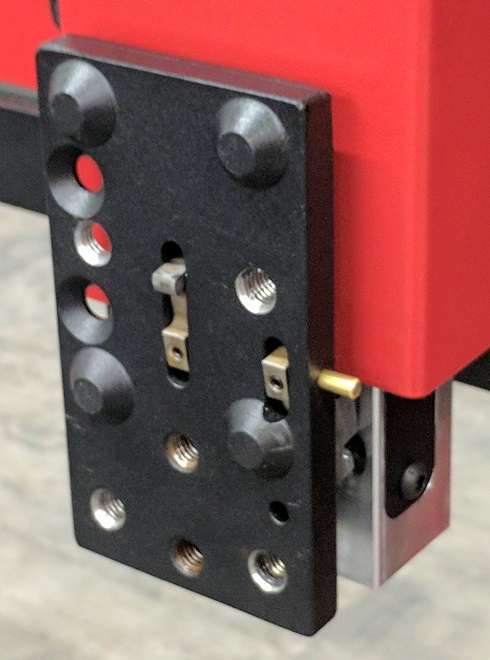
Adjusting the Breakaway Levers
Required Tools:
- 1.5 mm Hex Wrench
The magnetic base breakaway levers are supplied correctly adjusted. However, it may be necessary over the lifetime of the machine to ensure proper operation in the event of a collision.
Shown below is the magnetic base with the levers in the open position. There is a small spring installed into the outer lever. Be careful, this spring can easily fall out when the magnetic base is not installed in the machine.
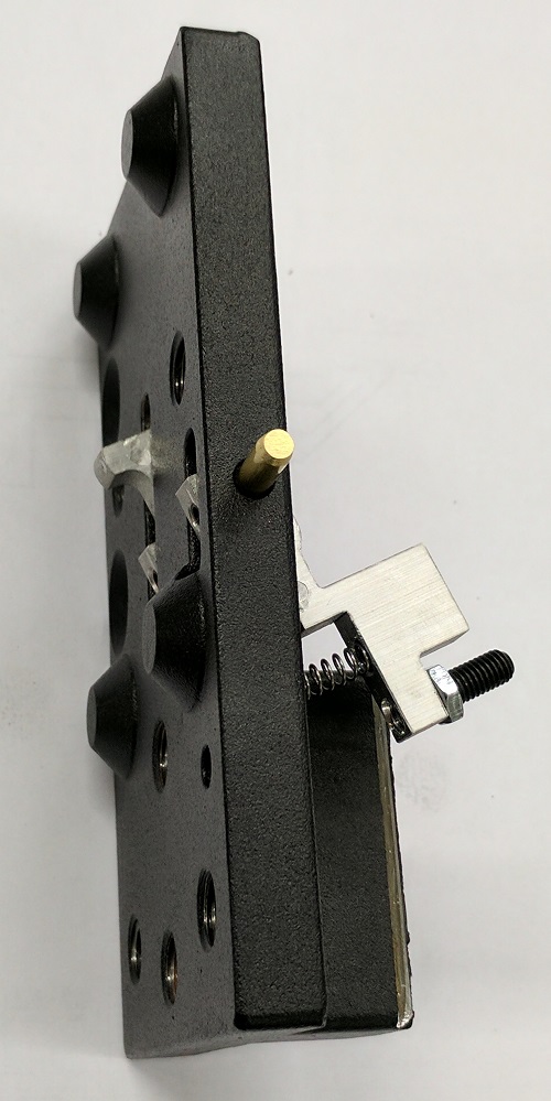
- Remove the spring and set it aside.
- Loosen the shaft locking set screws until the shaft easily slides through both levers.
- Place the inner and outer levers into their respective slots in the orientation shown.
- Press the brass shaft into the hole on the side of the magnetic base and through the levers until it stops.
- Slightly pull the shaft back out 1-2mm (1/16").
- Tighten the shaft locking set screw of the inner lever. Be careful not to overtighten or you may strip the head of the set screw.
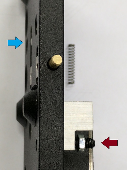
- Adjust the outer lever's set screw (red arrow) in as far as possible without protruding into the magnetic base.
- Press the outer lever flush against the rear face of the magnetic base and hold.
- Rotate the inner lever until the upper bump is flush with the front surface of the magnetic base.
- Tighten the outer lever set screw.
Installing the Magnetic Base
Required Tools:
- 6 mm Hex Wrench
- Thread locking compound (non-permanent)
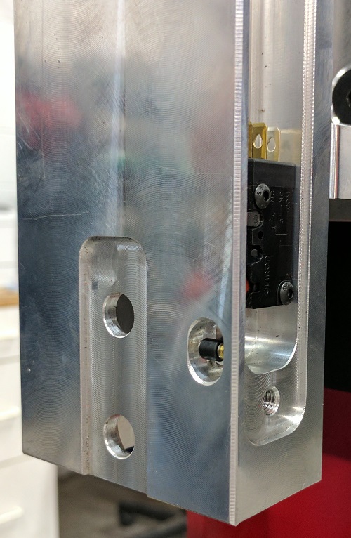
The Z-Axis beam has a precision machined slot in the lower front where the magnetic base is installed. The tight tolerance ensures the torch will be aligned vertically during operation. The magnetic base may have a small amount of residue left on the machined surface after the powder finishing process. If the magnetic base does not fit inside the machined slot, use a small flat file and scrape away any residual powder until it inserts smoothly.
Note: Design Update
Early production units did not have the machined slot in the Z-Axis beam. Please contact the sales department to get a replacement Z-Axis beam for your machine free of charge.

- Install the spring into the outer lever.
- Hold the lever closed and align the magnetic base in the machined slot.
- Tightly secure the magnetic base to the Z-Axis beam using the two (2) M10 x 25 mm flat head screws and a small amount of non-permanent thread locking compound.
Adjusting the Breakaway Switch
Required Tools:
- 3 mm Hex Wrench
- 8 mm Wrench
The torch breakaway switch is mounted in the slot on the right side of the Z-Axis beam. During operation, the long set screw in the outer lever makes light contact with the switch's roller. When the torch is removed, the spring pushes the setscrew into the switch roller and triggers the fault condition.
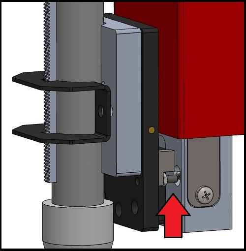
- Install the magnetic torch mount onto the magnetic base.
- Using a 3 mm hex wrench, slowly turn the set screw in until it makes contact with the roller. Do not extend the set screw far enough to depress the switch or false breakaway errors are likely to occur.
- Use the 8mm wrench to tighten the 5mm locking nut against the aluminum outer lever arm while holding the set screw in position with the 3 mm hex wrench.
When adjusted correctly, the Torch Breakaway Indicator will not be lit when the magnetic torch mount is in the magnetic base. Upon removing the torch mount, the indicator should be lit, and power to the amplifiers will be removed. If not, adjust the breakaway switch and retest.