About the Default Tables
Selecting the proper consumables to use when plasma cutting is crucial to obtaining above average cut quality. When you use the Plasma Settings Control, the default values are directly from the operator's manual of the plasma unit. These recommendations are just that - recommendations. If you find that a certain material cuts better with different settings, or even different consumables entirely, then by all means use your best judgement.
Note
The plasma manufacturer settings are the result of large experiments with many test cuts. They include the balance between quality of cut, and consumable life. While you may be able to obtain a higher quality cut than the factory settings, be aware the consumable life may be affected.
Size Your Consumables
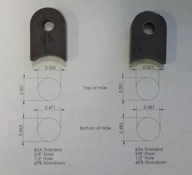
Choose the proper consumables for the material and thickness you are cutting. A decrease in cut amperage typically leads to a decrease in taper. The following image shows the same part cut from mild steel with recommended settings using both 65A shielded consumables, and 85A shielded consumables. The 85A part has much more taper, but the time required to cut the part was decreased.

Note
These parts were cut without tweaking parameters intentionally. If the hole taper was too large, we could probably do a little better by lowering the speed and cut voltage. Remember, plasma is not a milling machine or a laser. You will not get perfectly concentric, +/-0.001" (0.025 mm) toleranced holes. Design your part tolerances accordingly, and drill or machine holes when necessary.
The Speed / Quality Trade-off
To minimize taper during a cut, we want the plasma arc to remain "stiff" and well-formed. Using shielded consumables goes a long way to producing the proper conditions, but they operate best inside certain speed ranges. As our speed increases, the plasma arc begins to lag behind the torch. When the torch reaches a corner, these affects are easily seen on a finished part.
Examining the cutting tables closely, you can see one of the main differences between cut qualities is a decrease in Cut Feed as the quality increases.
Taking this one step further, for small contours and holes, slow down even more! We recommend slowing down to 60% of the recommended Cut Feed as a starting point. Since the Arc Voltage will be much greater during this slowdown, we must disable ATHC to avoid a crash.
SheetCam Path Rules
The post processor provided automatically handles ATHC when the desired speed is set below 99% of nominal due to a SheetCam path rule. When you make a custom path rule, just set the desired slow down percentage and the post processor will do the rest.
Cut Height / Voltage
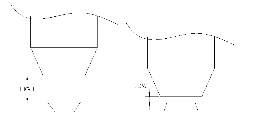
Adjusting Cut Height, or Voltage when ATHC is enabled, gives another method of adjusting the taper in the finished cut:
- Too high will produce a large taper with the top being larger than the bottom.
- Too low will produce a large taper with the top being smaller than the bottom.

No Lead-Out
Lead-outs are not always necessary with a plasma cut. If the path cuts a hole for instance, the slug can fall away and the plasma arc is quickly taken to open-circuit voltage during the lead-out off the edge of the plate. This can reduce the life of your consumables.
Overcut
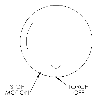
Overcut is used to describe the process where the torch is kept in motion while the plasma is turning off. This spreads out the affected heat zone compared to turning off the arc while stationary, reducing the amount of overburn near the end of the contour cut.

Cutting Side
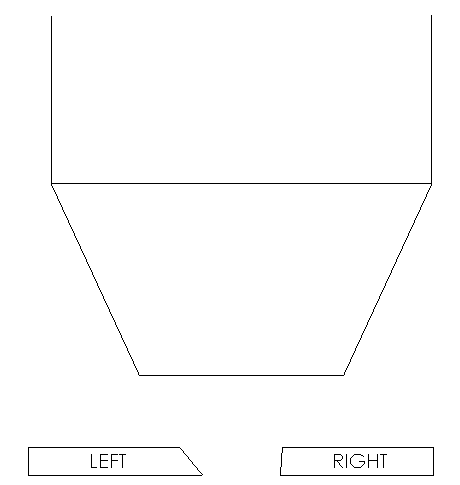
Certain manufacturers recommend cutting on one "side", typically the right-side, of the plasma arc. For many reasons, the arc wall is squarer which produces less taper in the finished cut.

To cut on the right-side of the arc, imagine yourself walking along the cut path and dragging your right hand along the finished part. Simply, this means:
- Cut counterclockwise on internal contours
- Cut clockwise on external contours