Receiving the Machine
Be ready when your machine arrives
MAD CNC Plasma Tables are very heavy when shipped, ranging from 1300lbs. to 2900lbs. Ensure you have a suitable lift available before your scheduled delivery.
When the pallet arrives, thoroughly inspect for damage before accepting delivery. If you find damage, refuse delivery and contact JD Squared. If you are using a forklift, lift the pallet from the dedicated fork pockets.
Removing from the Pallet
Required Tools:
- 9/16" Socket
- Impact Driver (Optional)
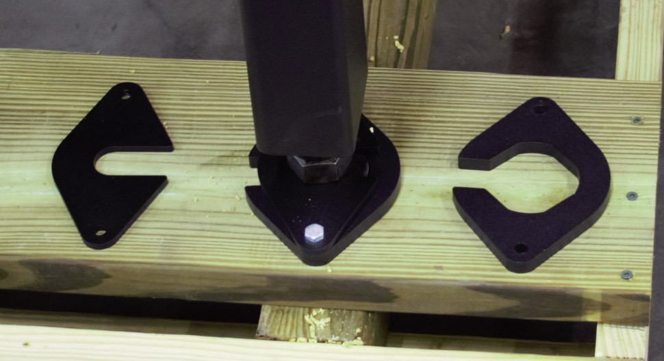
Remove the four shipping anchors from the feet.
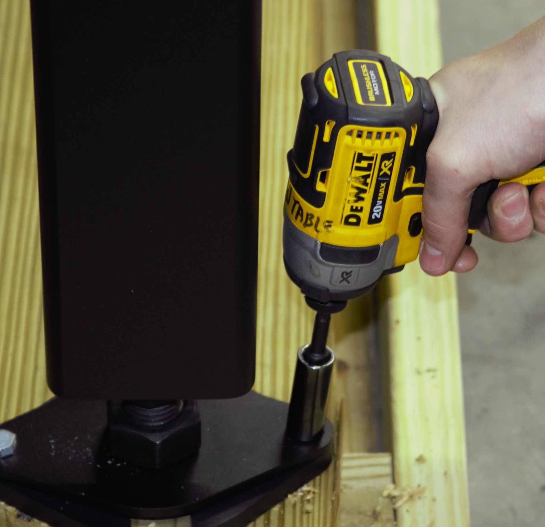
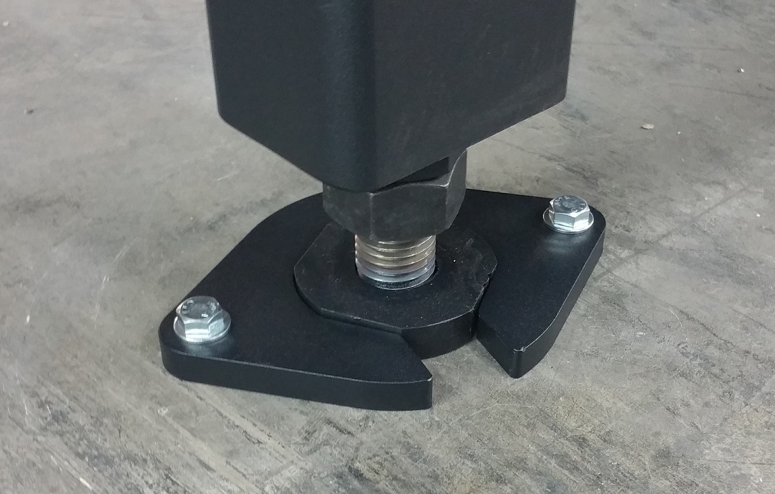
- Retain the lower plates surrounding the feet shown on the right. These can be reused to anchor the machine to the floor.
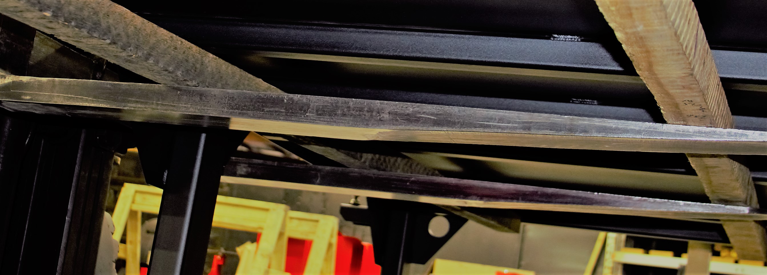
- Forklift - Fork from the center of the machine on the side opposite the electrical panel. Lift the machine off the pallet using two pieces of wood as support for forks.
- Position the machine in the final install location before continuing.
Installation Checklist
The following tasks must be performed to prepare the machine for operation:
- Remove Shipping Brackets
- Level the machine
- Attach Support Brace (5' x 10' Only)
- Assemble the Operator Station
- Connect Electrical Utilities
- Fill with Cutting Fluid (Optional)
Remove Shipping Brackets
Shipping brackets are attached using hex bolts and flange nuts allowing removal with one wrench. After breaking loose the exposed bolt head, put pressure on the nut with your finger and spin out the bolt. Retain the shipping brackets and their hardware in case the machine is relocated in the future.
Required Tools:
- 10 mm Wrench
- 13 mm Wrench
- 30 mm Wrench
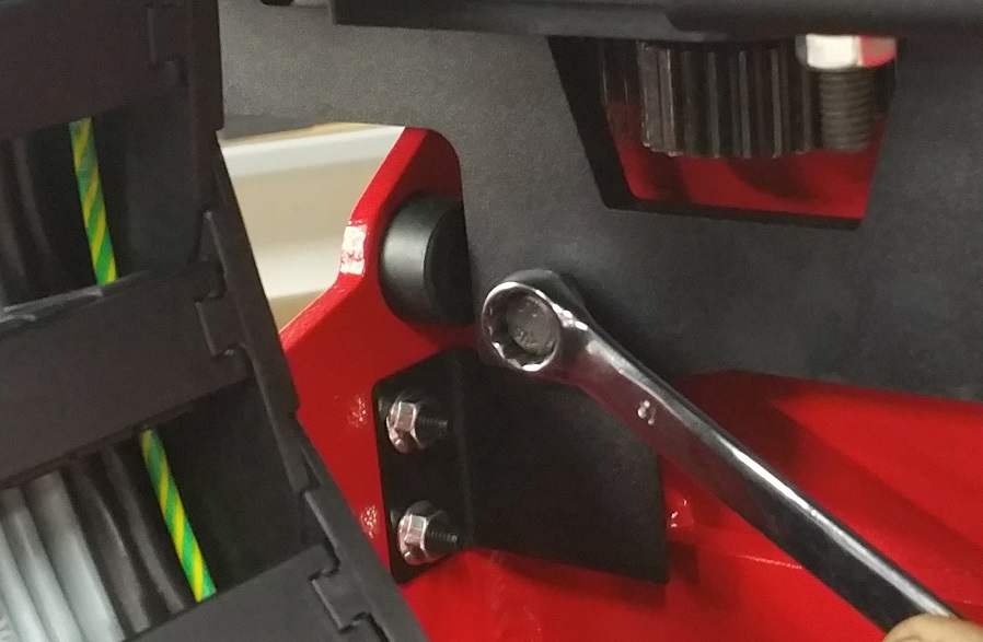
X Shipping Bracket
- Remove the two bolts attaching the shipping bracket to the gantry using a 10 mm wrench.
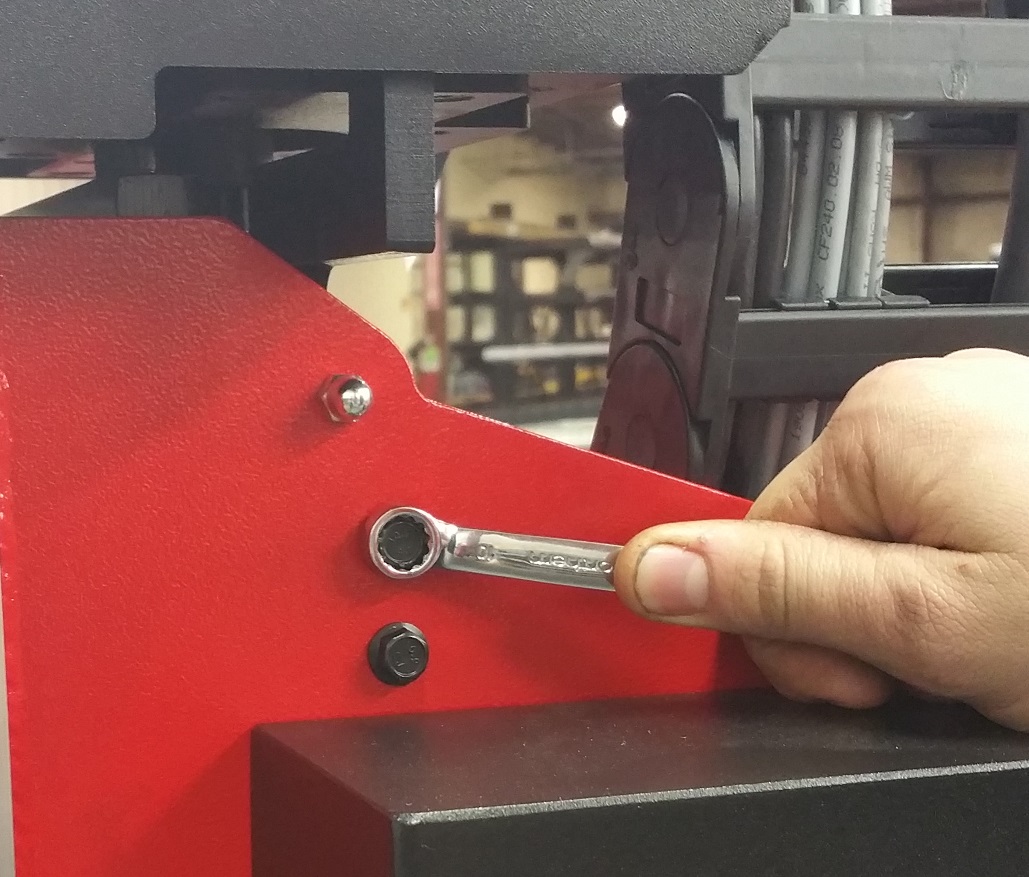
- Remove the bolt attaching the shipping bracket to the X-Carriage using a 13 mm wrench.
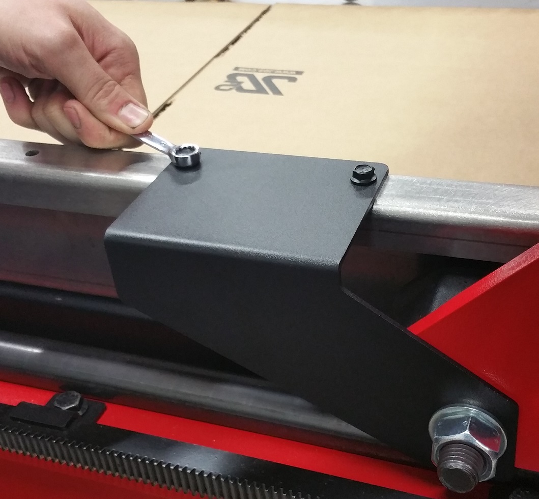
Y Shipping Brackets
- Use a 10 mm wrench to remove the two bolts attaching the shipping bracket to the table.
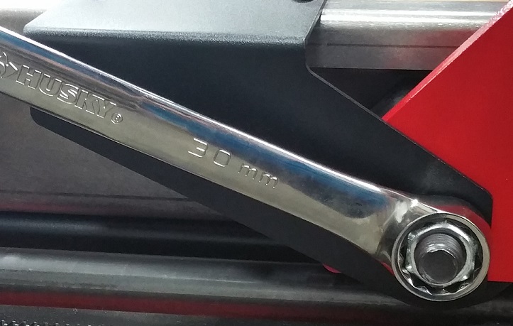
- Use a 30 mm wrench to remove the nut attaching the shipping bracket to the gantry.
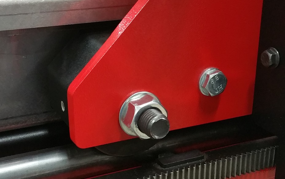
- Replace the nut on the gantry and tighten.
Level the Machine
Note
The machine does not need to be perfectly level, but it should be close. More importantly, ensure the gantry rollers contact the rails evenly along the full length of travel.
Required Tools:
- 6' Long Bubble Level
- 46 mm Wrench (Large Adjustable)
- (Optional) Leveling Kick-Plate
Leveling Kick-Plate
The kick-plate is made from steel and may damage some floor coatings as it rotates. Consider placing thin shims between the floor and the plate to lift the arms above any coating.
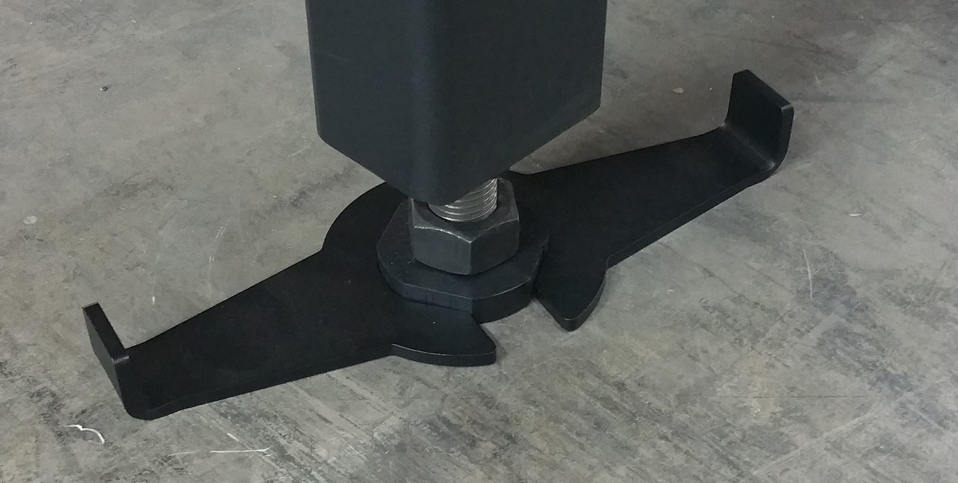
- If the machine has six legs, raise the center two so the machine rests on only the four outer corner legs.
- Slowly push the gantry until it is at the front of the machine.
- Place the level on top of the 12 mm rod on the gantry X-Axis.
- Adjust the front legs until the machine is level along the X-Axis in the front.
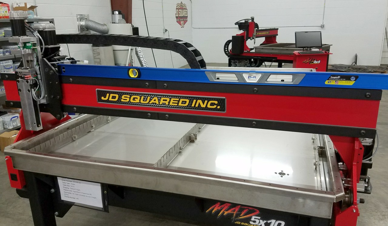
- Place the level across the Y-Beams near the rear of the machine.
- Adjust the rear feet until the machine is level along the X-Axis in the rear.
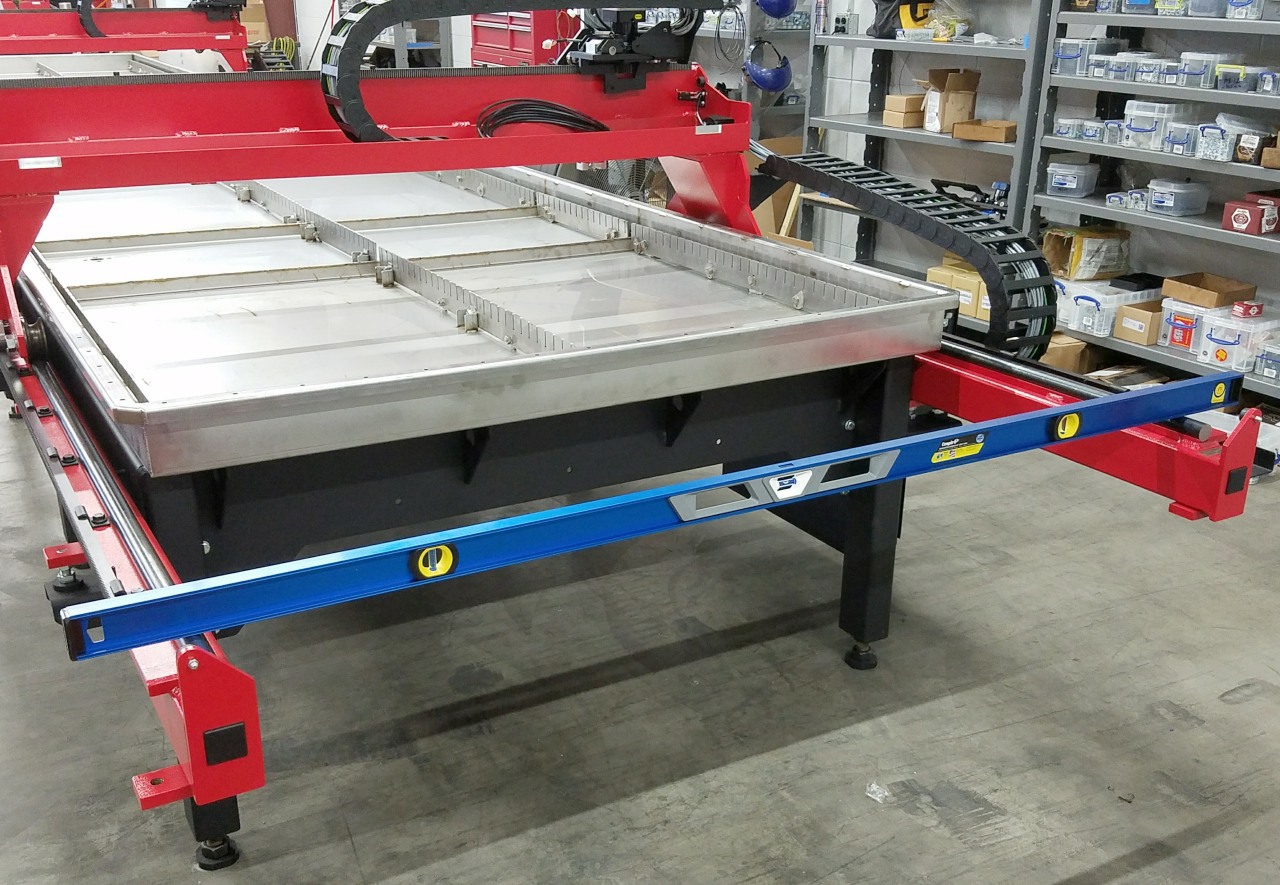
- Place the level along a Y-Beam.
- Adjust both rear feet together until the machine is level along the Y-Axis.
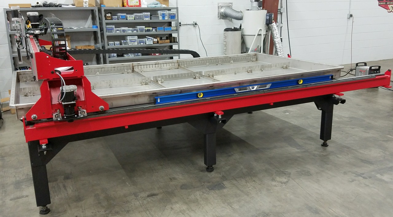
- Replace the level across the Y-Beams in the rear of the machine.
- If necessary, correct the leg opposite of the Y-Beam used to level the Y-Axis until the machine is level along the X-Axis again.
- Move the gantry along the Y-Beams to multiple locations checking for friction between the rollers and the Y-Beam rails. If any roller turns freely, the machine is not sufficiently level. If the condition persists after checking the machine's rough level, the Y-Beams may need to be adjusted.
- If equipped, lower the two center feet until they contact the floor.
- Tighten locknuts on every foot.
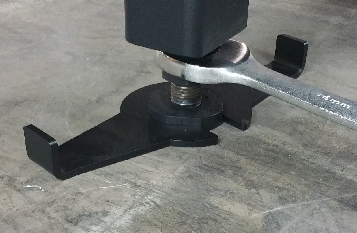
- (Optional) Position the four anchor plates and secure them to the floor.
Attach Support Brace (5' x 10' Only)
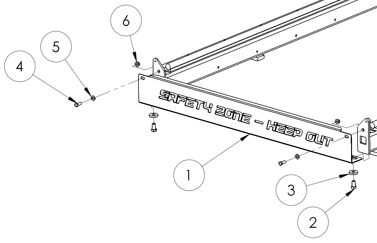
Due to shipping constraints, the MAD 5' x 10' requires assembling the rear support brace to the machine after leveling.
Required Tools
- 19 mm Wrench
- 24 mm Wrench
Required Materials
| Assembly Number | Description | Quantity |
|---|---|---|
| 1 | Support Brace | 1 |
| 2 | M16 x 30 mm Bolt | 2 |
| 3 | Thick Washer | 2 |
| 4 | M12 x 30 mm Bolt | 2 |
| 5 | M12 Washer | 2 |
| 6 | M12 Flange Nut | 2 |
Position the support brace against the rear of the two Y-Beams, and attach with hardware as shown.
Assemble the Operator Station
Note
Do not overtighten zip ties holding cables. There is a large amount of leverage and the internal wires can be crushed.
Position the operator stand near the front left of the machine. In this location, the machine X-Axis positive will be to your right, and the Y-Axis positive will be moving away from you.
Connect the Emergency Stop Cable
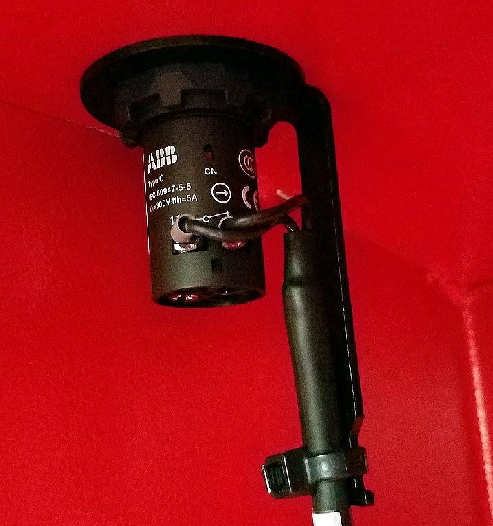
The Emergency Stop Button is preassembled to the operator station at the factory. Check it for shipping damage before proceeding.
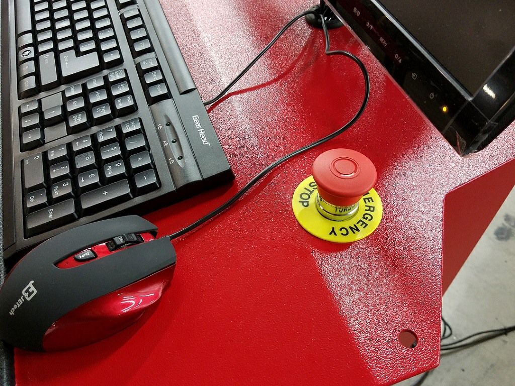
- Route one end of the Emergency Stop cable (S3.194C) up through the cable hole in the internal shelf, and attach the two ends to the preinstalled Emergency Stop Button terminals.
- Secure the cable to the strain relief bracket with a zip tie.
Assemble the Monitor and PC
Note
The monitor / PC bracket may have been preinstalled to the stand at the factory. You will still need to mount the monitor to the bracket before mounting the PC.
Required Tools:
- Phillips head screw driver
- 5 mm Hex Key
- 13 mm Wrench
The standard four bolt VESA mount pattern on the back of the monitor is used to anchor to the combination monitor and PC mounting bracket.
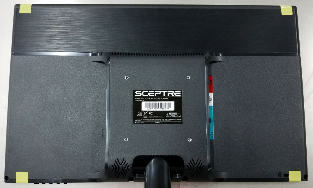
- Attach the combination bracket to the four VESA mount holes using a screw driver and M4x6mm screws.
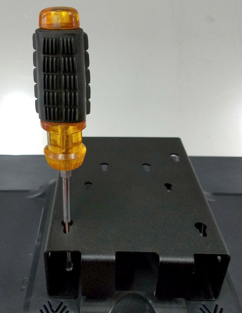
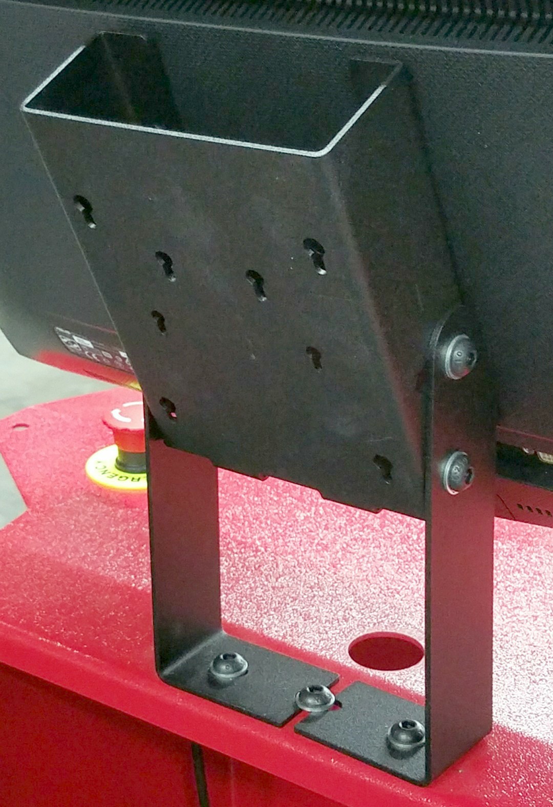
- If the PC bracket is not assembled to the stand, install it now using seven M8 button head screws, washers, and flange nuts. Adjust the monitor and stand for a suitable viewing position, generally tilted all the way back for standing operation. The slots are sized to allow for leveling the monitor horizontally.
- Insert the two rubber grommets in the cable holes.
- Attach the monitor A/C power cord and route it down through the top access hole and the access hole in the shelf.
- Attach the A/C power cord to the PC's power supply brick and insert it into the bracket behind the monitor as shown. Route this A/C power cord down with the monitor's A/C power cord. Route the smaller cable down through the bottom of the bracket leaving it on the top shelf.
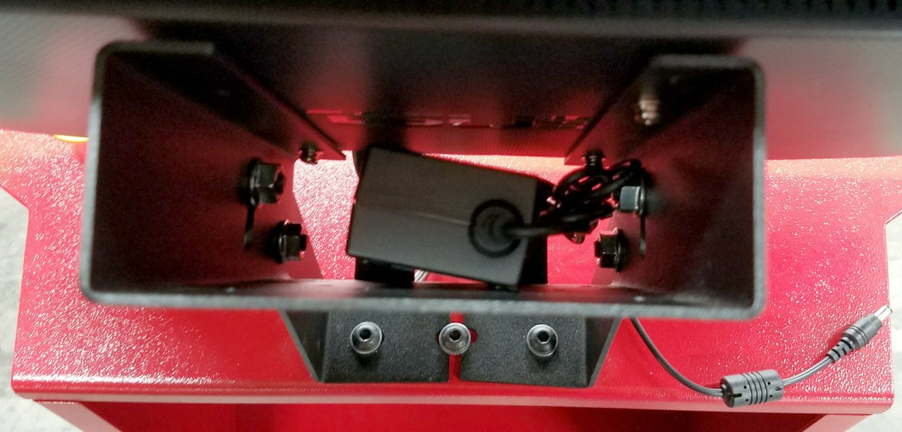
- Mount the PC to the stand by sliding the two screws into the keyhole slots and pushing down until secure.
- Attach the WIFI antennas.
- Attach the barrel connector from the power cord inserted into the bracket earlier.
- Connect the HDMI cable from the PC to the monitor.
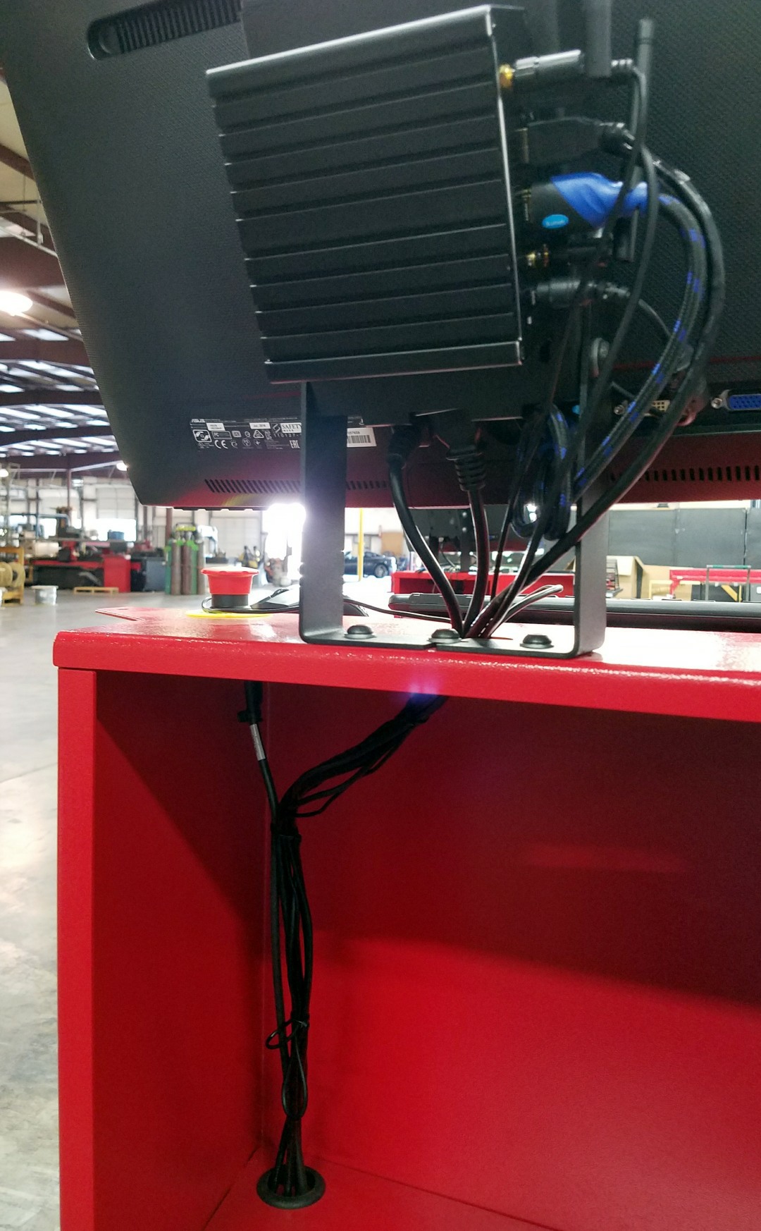
- Place the keyboard and mouse on the operator stand and route the cables down through the access hole, and then back up. This puts extra cable length in the shelf cavity. Connect the two USB cables to ports on the same side as the antennas on the PC.
- Route the 25' Ethernet cable (S3.230C) up through the cable access holes and plug one end into the Ethernet port nearest the middle of the PC. This port is configured by default to communicate with the machine, and must not be used for any other purpose. A wired Ethernet connection for a local network may be plugged into the second Ethernet port.
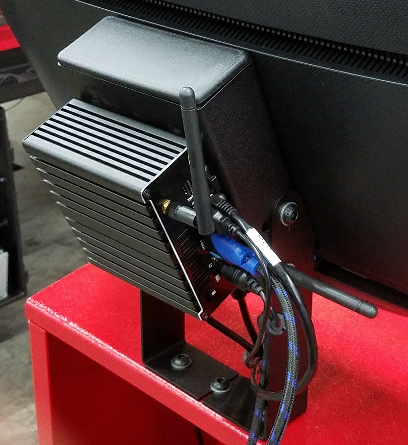
- Tidy the cable connections inside the cabinet using zip ties using the following image as a reference:
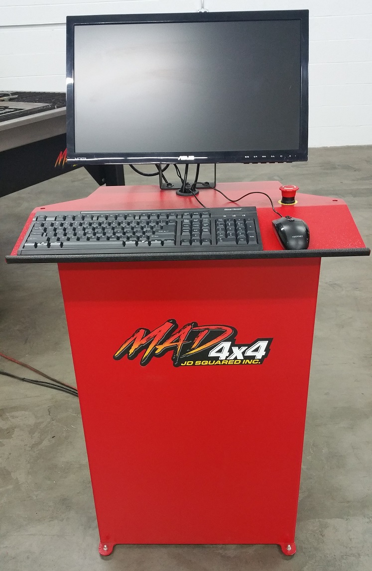
The assembled operator station:
Connect the Operator Station to the Control
Version 2 Labeling
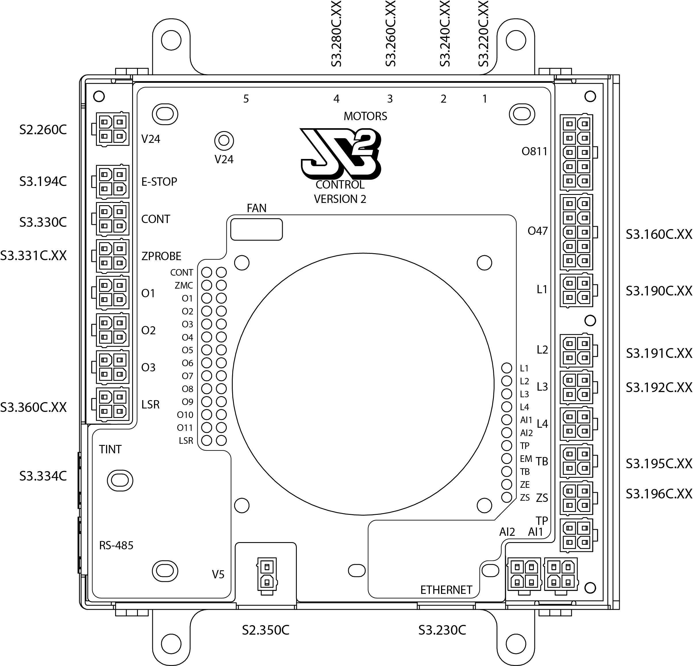
The Control Board (PCB1) and the Torch Interface (PCB2) have labels printed on the covers to identify receptacles. Make sure you are inserting the proper cable in the correct location.
- Run the Emergency Stop cable (S3.194C) and the shielded Ethernet cable (S3.230C) along the floor to the electrical panel housing the machine controller (control panel). Route these cables in a safe place so they will not be crushed by walking operators or when loading material.
- Insert the two cables through the gasket on the bottom of the control panel, and route the cables up the right-hand side of the box along the guides.
- Route the Ethernet cable (S3.230C) into the horizontal wire duct and connect it to the Ethernet port on the bottom of the control board (PCB1).
- Route the Emergency Stop cable (S3.194C) into the into the horizontal wire duct, up the vertical wire duct, and connect to the port on the left side of the control board (PCB1) marked E-STOP.
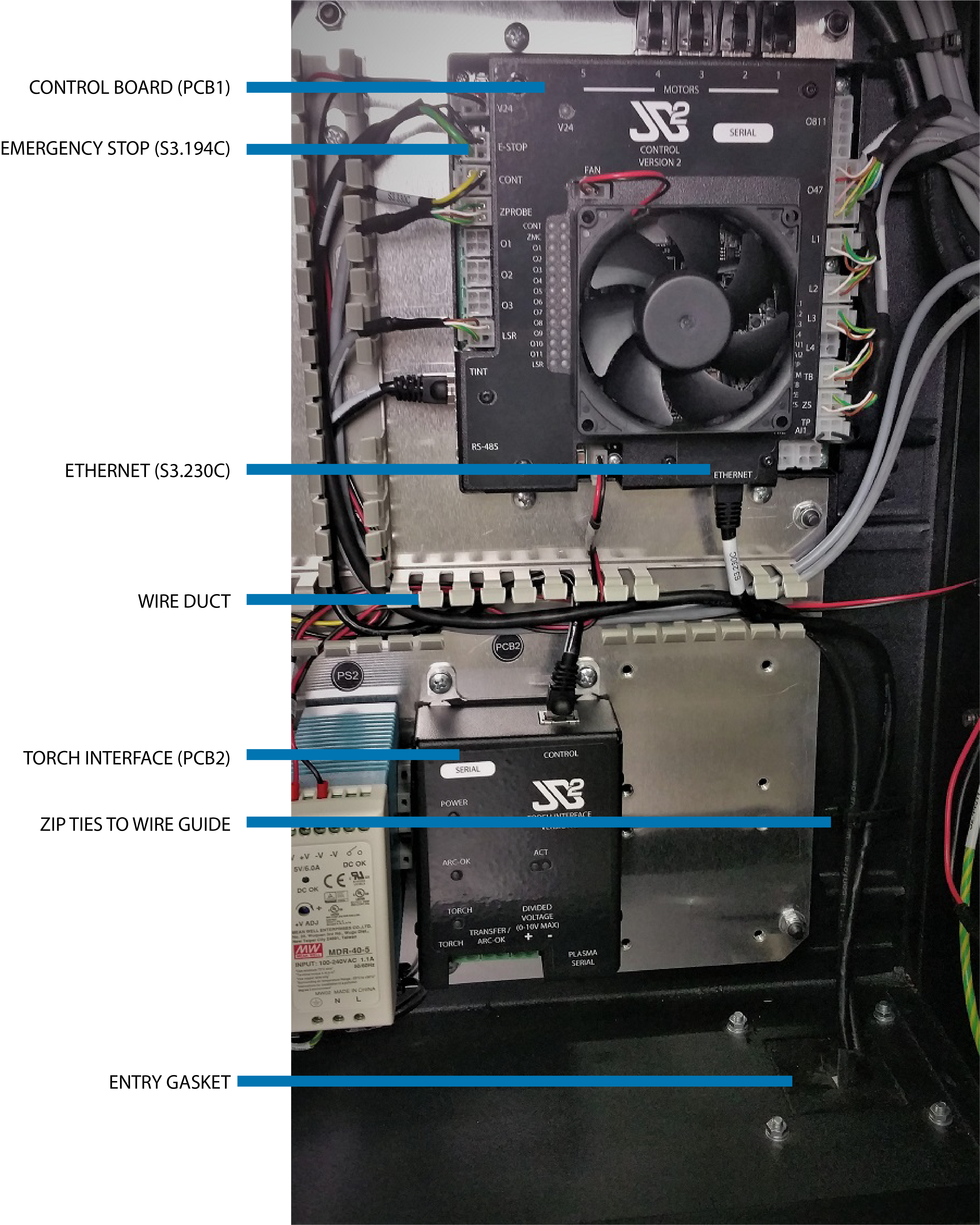
You may verify these connections against the schematic diagram or use this printable template, reproduced here:
Connect Electrical Utilities
Danger!
The electrical panel requires connection to hazardous voltages. These operations should be performed by qualified personnel only. Ensure installation meets local code requirements.
Power input must be between 190VAC-250VAC 50Hz/60Hz. Supplemental protection is provided at 15A, but a primary source of protection, e.g., a branch circuit breaker, is required inline with the supply. Voltages outside of the specified range will damage the machine. It is highly recommended to include a source of surge protection if installing in an area prone to electrical storms. If the installation will share a distribution panel with a phase converter (rotary, or VFD) which can back feed voltage, ensure the voltage supply never violates the acceptable range under all loading conditions.
Electrical Installation Instructions
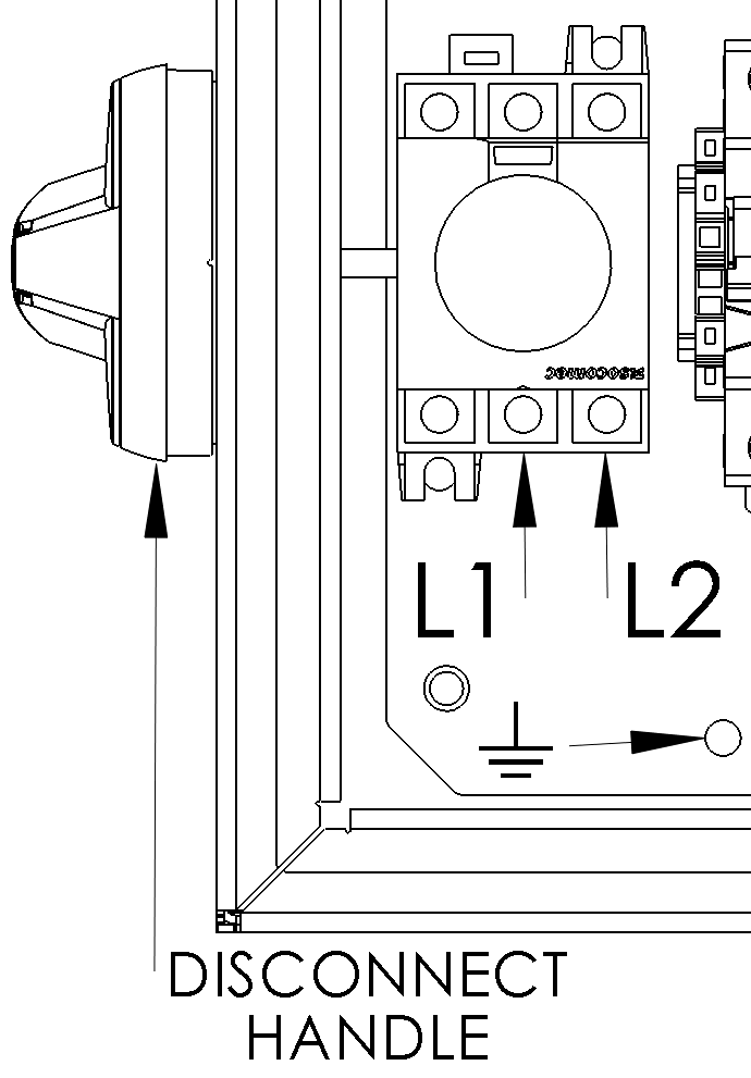
The electrical connections are shown in following figure. The feed conductors must be no smaller than 12GA copper. Connect the electrical supply ground to the backplane using the M5 bolt marked with the ground indicator. Please refer to the schematic for more details.
Connect Plasma Unit
To connect the required utilities for your plasma power supply, please refer to your specific manufacturer's manual. There are two additional connections required for the machine to communicate to the plasma power supply.
Grounding Connections
When cutting a part, high currents are created by the plasma unit. We must provide a safe return path to protect the sensitive electronics in the machine.
Grounding Rod
You may choose to install a dedicated grounding rod for the machine. Connect it directly to the machine bonding bar with a minimum of 6GA copper wire.
The primary return location is the bonding bar mounted near the electrical panel. Connect the plasma units ground cable (+) lug to one of the unused locations on the bonding bar using the factory supplied hardware (M8x1.25mm). If the work clamp is attached to this cable, remove and install to the second grounding cable supplied. Connect the second ground cable with the work clamp to the bond bar in the remaining unused location. This work clamp must be attached directly to the material being cut during operation.
Always Connect the Work Clamp
Failure to connect the grounding clamp directly to the work piece may cause permanent damage to the machine or plasma supply.

Torch Interface Connections (Version 2)
The version 2 torch interface has extra features and a different connection scheme compared to the previous version. Before connecting your plasma power supply to the torch interface card, ensure the proper voltage divider (50:1) is selected in the plasma power supply per the manufacturer’s instructions. If the plasma unit does not have an internal divider, an external division circuit is required.
Double Check Voltage Settings
Supplying an incorrect voltage range may cause permanent damage to the torch interface. Double check the divisor settings inside your plasma unit! For a Version 2 interface, the divisor must be 50:1.
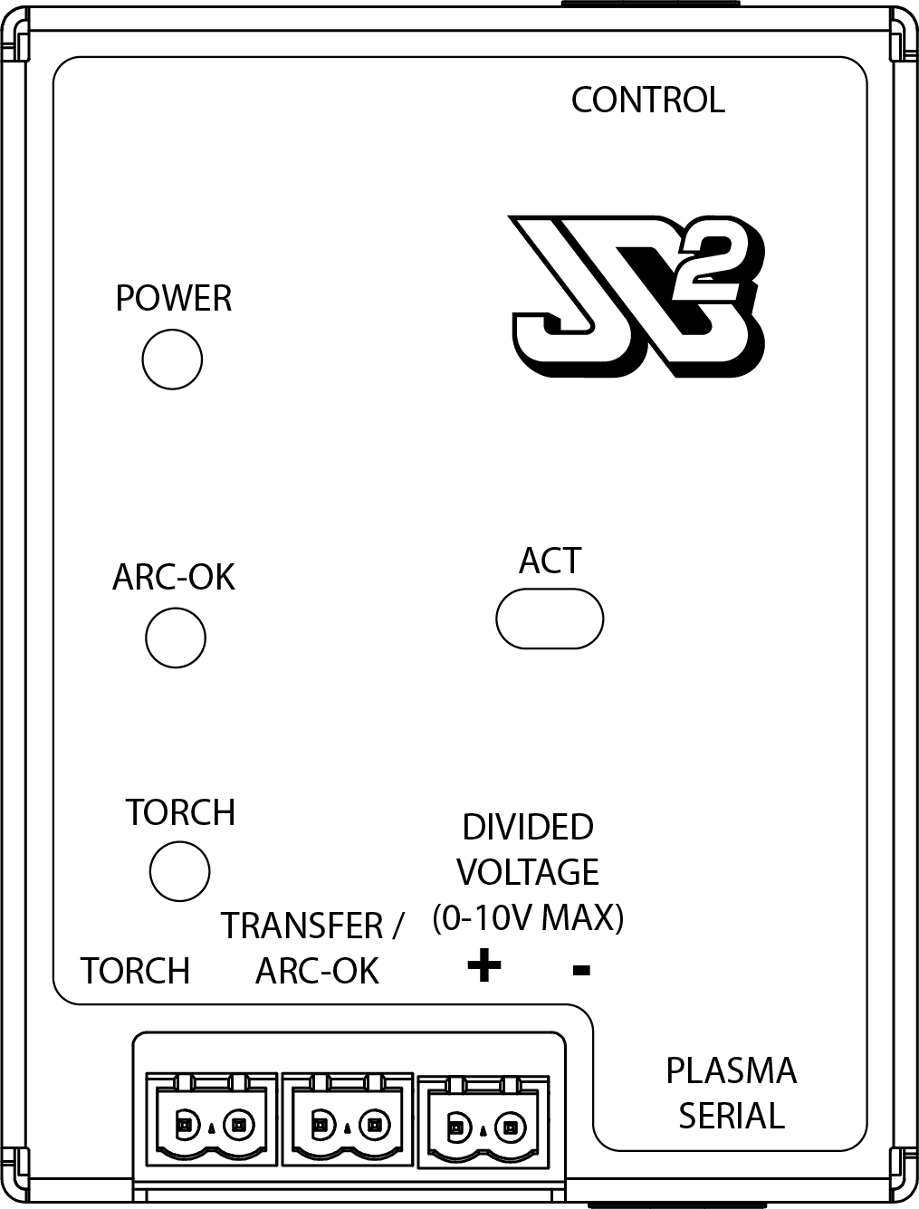
You must refer to your plasma power supply instruction manual or addendum to verify which wires perform which function. Any example connections for Hypertherm Powermax® and Thermal Dynamics Cutmaster® power supplies are provided as a reference only and should be verified by checking the plasma unit operation manual.
Prepare Machine Interface Cable
The terminal plugs used on the torch interface have screw terminals for wires. There are three plugs corresponding to the three wire pairs.
Note
If you have purchased a plasma unit and the machine interface cable through JD Squared, the terminal plugs will be correctly assembled at the factory.
To manually prepare a machine interface cable for connection:
- Cut off and discard spade terminals on the end of the internal wires if installed.
- Strip the outer jacket back to reveal the inner wires. Be careful not to cut the jacket of any of the internal wires.
- If the internal wires are in shielded pairs, carefully remove the foil shield back approximately 2” (50mm) from the end of the wire pair.
- Strip the end of each wire approximately 3/8” (9.5mm).
- Insert the stripped end into the screw terminal box and tighten the screw.
- Gently pull the wire to make sure it is securely attached.
- Repeat, installing one screw terminal plug to each of the three pairs.
Connect Control Signals
There are two control signals used to interact with the power supply unit, typically labeled Transfer Start / Arc Okay and Torch Start. The version 2 torch interface has no polarity on the Transfer Start / Arc Okay or the Torch Start signals. Just make sure to put the correct wire pairs into the matching plug.
- Insert the machine interface cable through the gasket on the bottom of the control panel and pull along the bottom of the panel to the interface pcb (PCB2).
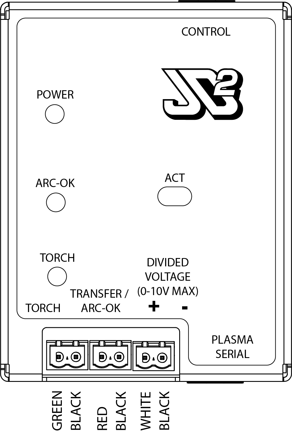
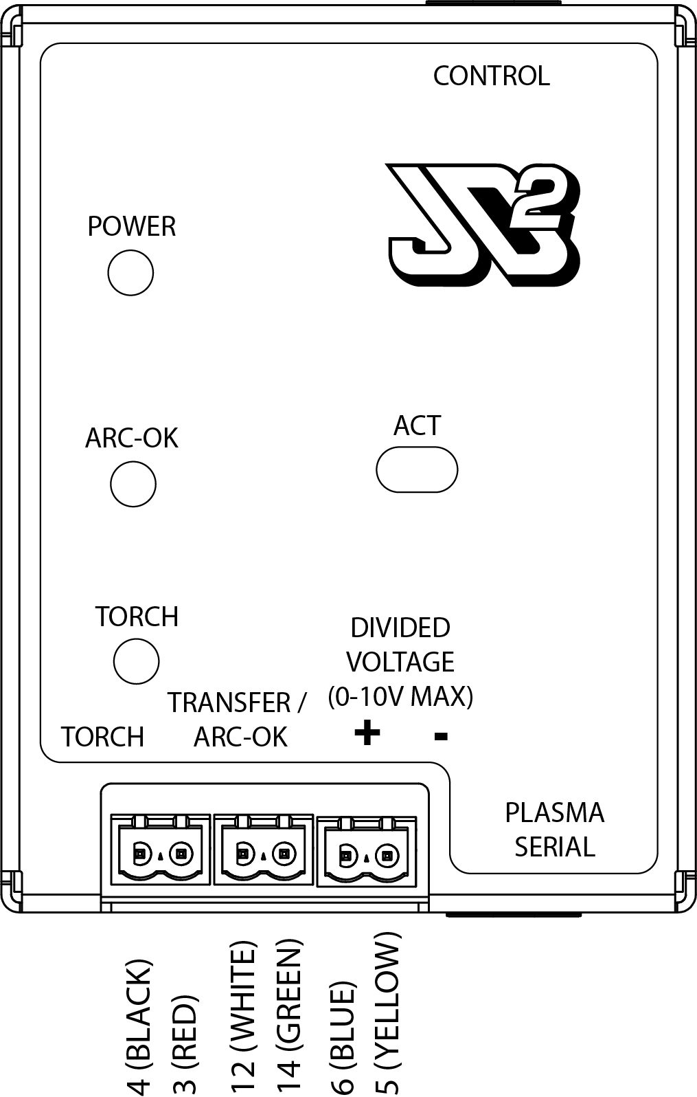
- Connect the Transfer Start / Arc Okay pair to the plug marked TRANSFER / ARC-OK.
- Connect the Torch Start pair to the plug marked TORCH.
Connect the Divided Arc Voltage
The voltage feedback (Divided Arc Voltage) is polarized. Make sure you observe the polarity of the connecting wires. The left pin is positive (marked +).
Plasma Unit Divisor
Check the plasma unit operator's manual, and ensure the unit is set for arc voltage divisor of 50:1!
- Connect the divided voltage feedback pair to the plug marked Divided Voltage.
Hypertherm Powermax® Example Connections
When connecting a Hypertherm Powermax® plasma to a version 2 control board, there are three wire pairs. Each pair is grouped inside an inner shield; one color with its corresponding black reference wire. Keep the black wire together with its paired color.
Thermal Dynamics Cutmaster®
When connecting a Thermal Dynamics Cutmaster® plasma to a version 2 control board, there are three wire pairs used, and two wires to cap. Each wire is numbered and colored. Apply insulating caps to unused wires.
Torch Interface Connections (Version 1)
The version 1 torch interface is designed to be as generic as possible. Before connecting your plasma power supply to the torch interface card, ensure the proper voltage divider is selected in the plasma power supply per the manufacturer’s instructions.
Double Check Voltage Settings
Supplying an incorrect voltage range may cause permanent damage to the torch interface. Double check the divisor settings inside your plasma unit!
Connecting a Wire to the Torch Interface
The terminal blocks used on the torch interface are spring loaded. To connect a wire, strip the end approximately 3/8” (9.5mm). Depress the spring button fully and insert the stripped wire. Releasing the spring button will make the electrical connection. Gently pull the wire to make sure it is securely attached. The torch interface has no polarity that needs to be observed. Just make sure to put the correct wire pairs into the matching terminal pairs.
You must refer to your plasma power supply instruction manual or addendum to verify which wires perform which function. Any example connections for Hypertherm Powermax® and Thermal Dynamics Cutmaster® power supplies are provided as a reference only and should be verified by checking the plasma unit operation manual.
Prepare Machine Interface Cable
Note
If your machine interface cable has ferrules installed on the ends of the cable by JD Squared, you may skip this section.
To manually prepare a machine interface cable for connection:
- Cut off and discard spade terminals on the end of the internal wires if installed.
- Install a cable grip / clamp in the 1/2" (12mm) knockout hole located below the torch interface card.
- Pull enough cable through the grip to reach the accessory connector on the left side of the board.
- Strip the outer jacket back to reveal the inner wires. Be careful not to cut the jacket of any of the internal wires.
- If the internal wires are in shielded pairs, carefully remove the foil shield back approximately 2” (50mm) from the end of the wire pair.
Connect Control Signals
There are two control signals used to interact with the power supply unit, typically labeled Transfer Start / Arc Okay and Torch Start. A close-up picture of the terminal block on the PCB follows:
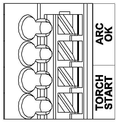
- Connect the Transfer Start / Arc Okay pair to the auxiliary terminal block in the locations marked ARC OK.
- Connect the Torch Start pair to the auxiliary terminal block in the locations marked TORCH START.
Choose the Correct Voltage Range
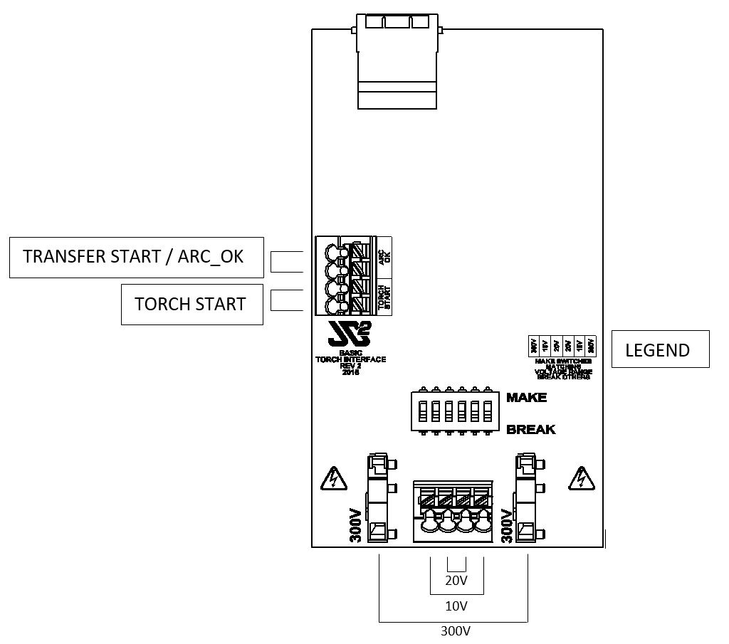
Check the plasma unit operator's manual or electrical placard for the maximum open circuit arc voltage. Typically, this value is 300VDC to 400VDC. Divide that number by the divisor selected inside the plasma unit to determine the divided arc voltage maximum. Pick the lowest voltage range on the torch interface board that is larger than this maximum voltage.
Example: With an open circuit arc voltage of 400V, and a plasma unit divisor of 50, the maximum divided arc voltage is (400V / 50) = 8V. We would choose the 0V-10V range on the torch interface.
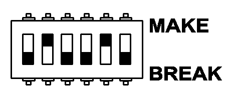
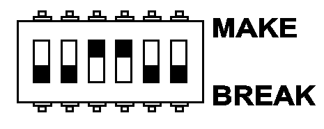
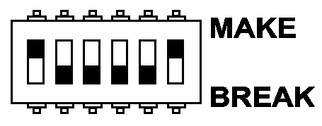
Select the appropriate voltage range on the torch interface board by sliding the switches to the MAKE position, and sliding all others to the BREAK position. The legend on the printed circuit board (PCB) gives the location of the switch in the pack for the given range. The three selectable ranges are:
| 0V - 10V | 0V - 20V | 0V - 300V |
|---|---|---|
 |
 |
 |
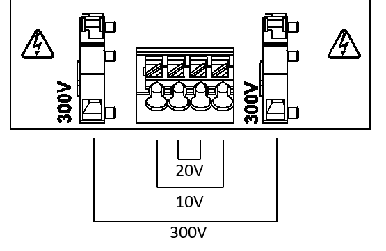
Next, install the divided voltage feedback leads from the plasma unit's machine interface cable to the corresponding terminals shown here:
Attach the Ohmic Probe Wire
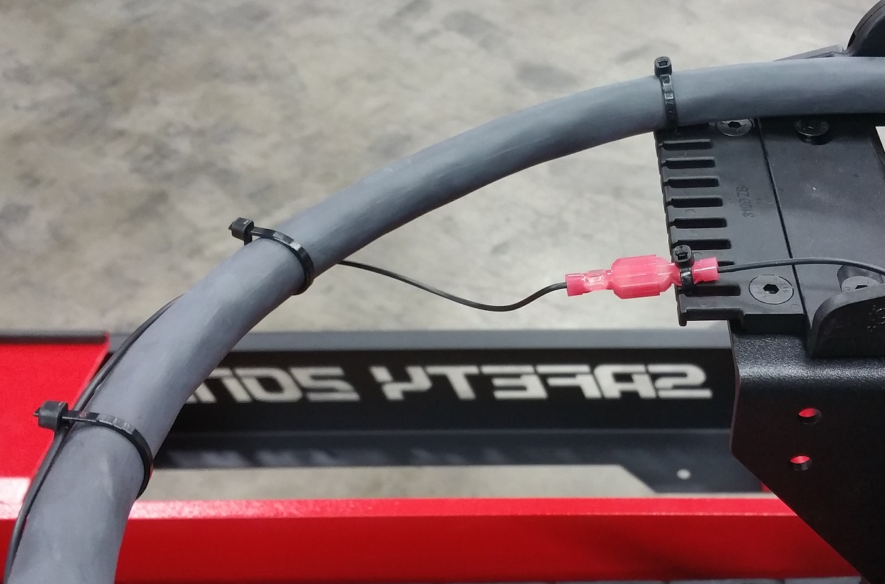
For the Ohmic probing system to function correctly, the small wire packaged separately must be connected from the Ohmic consumable cup to the provided connector in the cable guide on the back of the gantry. This wire is near the cutting zone, and is also considered a consumable. The spade terminals were intentionally chosen to be readily available at most home improvement stores.
- Ohmic consumables are readily identifiable by the clip that accepts a female spade connector. Connect one end of the cable to the consumables.
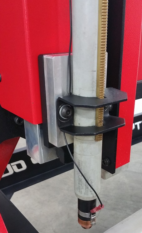
- Wrap the other end of the cable around the torch lead backwards until it reaches the mating spade connector in the cable guide and plug it in.
Install Slats
Required Tools:
- 17 mm Wrench x 2
- 19 mm Wrench x 2
The MAD CNC Plasma is shipped with a start pack of ten slats. Consult the following tables for size requirements for additional slats. Using dimensional hot rolled flat strap and cutting it with a bandsaw is recommended.
Air Table Slats
| Table Size | Slat Width | Slat Thickness | Slat Length | Maximum Slats |
|---|---|---|---|---|
| 4' x 4' | 3.0" (75mm) | 0.125" (3mm) | 50.0" (1270mm) | 34 |
| 4' x 8' | 3.0" (75mm) | 0.125" (3mm) | 50.0" (1270mm) | 66 |
| 5' x 10' | 3.0" (75mm) | 0.125" (3mm) | 62.5" (1587mm) | 80 |
Water Table Slats
| Table Size | Slat Width | Slat Thickness | Slat Length | Maximum Slats |
|---|---|---|---|---|
| 4' x 4' | 3.0" (75mm) | 0.125" (3mm) | 50.0" (1270mm) | 34 |
| 4' x 8' | 3.0" (75mm) | 0.125" (3mm) | 50.0" (1270mm) | 64 |
| 5' x 10' | 3.0" (75mm) | 0.125" (3mm) | 62" (1575mm) | 80 |
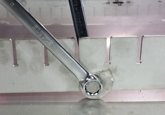
- Adjust the slat holders using two 17 mm wrenches until the work surface is level and perpendicular to the plasma head. Rotate the lifting cams to raise and lower that section of the slat holder.
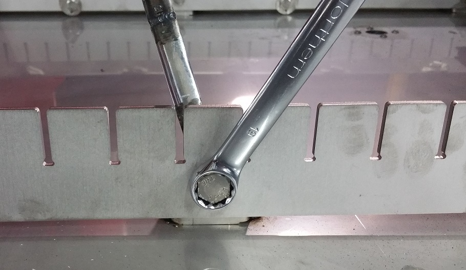
- Tighten the slotted nuts when complete using two 19 mm wrenches.
Slightly offsetting the center slat holders forward or back removes play when the slats are installed in their "straight" position. Loose slats will affect cutting quality by moving while the machine is operating.
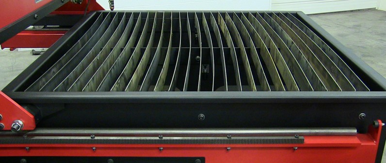
After adjusting the slat holders, install the desired number of slats in the configuration required. These slats are installed in an air table with a slight bow:
Fill with Cutting Fluid
Note
Before filling, make sure you have a drainage plan in place. Adding valves, plumbing, etc., to the drain plugs in the bottom of the table should be completed before filling with cutting fluid.
We recommend filling the water table with a plasma specific cutting fluid such as GreenCut® by LubeCorp. These additives help protect the mild steel support slats, prolong the life of the water bath, and provide an antibacterial chemistry. Plain water is also an acceptable fluid, but it will require much more frequent maintenance and cleaning due to the increased corrosion of the slats.
The maximum volumes of the water tables are approximately:
| Table Size | Maximum Volume |
|---|---|
| 4' x 4' | 49 gallons (185 liters) |
| 4' x 8' | 94 gallons (355 liters) |
| 5' x 10' | 145 gallons (548 liters) |
It is not necessary to fill the water table entirely. We operate our tables with the water down 0.5" (12mm) below the work piece. Water level is a hot topic and personal experience will dictate where you fill your table. Operate in a well-ventilated area, and be aware of the possibility of hydrogen build-up explosions when cutting with a water table.
Connect to the Internet and Schedule Your Startup
We highly recommend connecting the user interface PC to the internet. This simplifies applying software updates to the machine, and enables you to take advantage of your allotted start up tech support.
Before scheduling your startup call, read through the documentation included in this site, and checkout the videos on the JD Squared YouTube channel. That way, any questions you have remaining can be resolved during the call instead of only explaining the basic operation.